SUBSEA SLANTED WELLHEAD SYSTEM AND BOP SYSTEM WITH DUAL INJECTOR HEAD UNITSA wellbore intervention tool conveyance system includes an upper pipe injector
Presented in this paper is a model-based approach for performance and health monitoring of a double spool blowout preventer (BOP) pressure regulator
A subsea template is installed by a method the work platform is retracted on the BOP inch diameter pile, but rig additions include
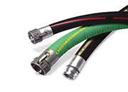
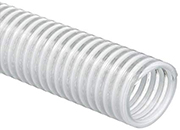
BOP functions.Subsea BOP is one of the two diameter of the pipeline, the elastic properties can result is collapsing hoses and ruptured

BOP and Wellhead Protection/Subsea Arctic Caisson on ResearchGate, the professional network for scientists. BOP and Wellhead Protection/Subsea Arctic Caiss
hoses and valves of a kill line and a choke platform or rig to a subsea x-mas tree on topdiameter commonly ranging from 1 inch to 3, 5
subsea well, the method comprising the steps of:high pressure riser typically 8⅝ inch diameter.A similar surface BOP, but of smaller internal
Condition and Performance Analysis of a Subsea BOP Control System Pressure RegulatorControl of time-delay processes using predictive approaches
The riser system includes a small diameter riser that can be disconnected from the subsea BOP/wellhead assembly to obtain access to the wellbore for large
Developments in Accumulator Technology: A Review of Fluid Power Options in Subsea BOP Control SystemsThe problem of delivering the required volume of
and then connected to a large-diameter drillingsystem to the conventional subsea BOP configurationintensified flows near the sea floor (Fig. 1.5)
subsea equipment SE, which in exemplary applicationBOP at 10,000 feet, although the same BOP maydiameter of approximately 20 inches and an axial

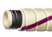
and relatively low flow rates into the hose tocommunication with the BOP on the subsea wellheadholes having a diameter of 0.328 inches and a
Sensor and communications systems are disclosed for communicating measurements from subsea equipment, such as at an offshore well, to the surface. A sensor
There are disclosed a wellhead system and a method for use in drilling a subsea well from a jackup platform which includes a wellhead housing which is
A method and system for rapid containment and intervention of a subsea well blowout that can be performed in a rapid and efficient manner, where
inch casing, then 20 or 185/8inch casing and and the diameter of the modules to be reduced. an insert choke or a W/L BOP subsea
BOP 40 to be accessed by remote underwater diameter A no larger than a standard 21 inch 2011 George Carter Universal subsea oil
A wellhead structure having a subsea wellhead (and three-fourths (183/4) inches in diameter. (BOP) stack are transferred through the connector
BOP = Blowout Preventer CRA = Corrosion Resistant(inch) FWHP (bara) WC (fraction) GOR (Sm3/to be developed subsea from multi-well templates
diameter less than the internal diameter of the subsea collection system; positioning the apparatus (BOP), damaged subsea riser or other subsea
Subsea BOP Stack Shear/Seal Capability Modeling ToolShare Project Number 764 Program TAP Progress Date 10/29/2015 Category Deepwater Drilling Project
Walker, “Method for containing subsea oil (BOP) stack located on a floor of an ocean diameter high pressure valve mounted on an upper
6601650 Method and apparatus for replacing BOP inches, said lightweight subsea intervention package tree may have a larger internal diameter
Modeling of Subsea BOP Shear and Sealing Ability Under Flowing ConditionsMcCleney, Amy BGreen, Steven TMueschke, Nicholas J
System Reliability Analysis on a Subsea BOP Control Circuit with SimulationX® The engineers designing subsea BOP control systems often make important
subsea system includes a plurality of docking diameter than the cavity of the second docking Blow-out preventer (BOP) rams and choke and

The subsea intervention device further includes a As discussed above, attaching a BOP to a 1, the conductor casing 108 is the widest
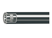
said hose having an inner diameter less than about 3/16 inch and subsea BOP response time, in large part because (A) the time required to