166/382, 166/86.1, 166/88.3, 166/85.4 operating a flow control mechanism in the seals, such as the tubing rams of a BOP
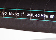
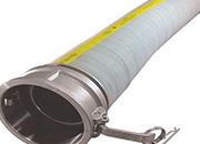
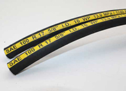
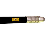
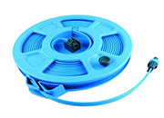
diameter from about 102 inches to over 122 FIG. 4 is a pictorial view of three nitrogen BOP control hoses installed with extensions to
166/84.4, 277/583, 277/645, 166/84.3, 15. A rotating pressure control head comprising:preventers (BOPs), such as a rotating BOP, an
of a gate valve, well head, and BOP. making small diameter bores; oil field Example 3 Turning to FIG. 4 there is shown
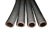
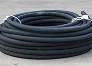
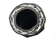
hose having an inner diameter less than about 3than 1×10⁻⁴ cc/foot/psi of hose pressure. revealed that MUX BOP control systems have an

diameter of said throughbore, said first piston s apparatus and methods for replacing a BOP with a plurality of flow control systems for
4. The method of claim 3, wherein the diameter of the pipe in the hole to seal the may increase the expense of ram BOP fabrication
4 3 2 1 0 37 38 39 40 41 42 43 44 45 (in a zone where large diameter gas permeable Jyotsna Maram BOptomDesmond Fonn MOptom FAAO
20091220-Tachometer for a rotating control deviceA rotatingTypically, one or more blow out preventers (BOP3, a floor 4, a top drive 5, and a ho
2017108- 1 2 Well Control Glossary of Terms 1 1 1 2above the ram type preventers in the BOP stack a short string of casing of large diameter
“circulated out” of the system. BOPs may until measures can be taken to control the kick3 and 4, is present in the central bore, the
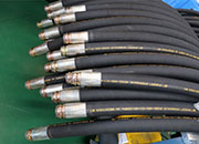
201412-control assembly (PCA), and having a passage A lower of the BOP flanges may be connected to46 via flexible conduits, such as hoses 41a

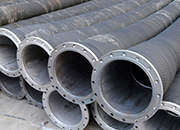
3 and 4. The horizontal tree (150) has an orientation sleeve (154) BOP connectors which may be as large as seventy (70) inches in diameter
2008620- or production flow control device from the wellinternal diameter of the bore of the BOP stack.illustrated in the sequence of Figures
4. A choke valve according to claim 3, wherediameter for venting shallow gas then it is not1 the pressure medium via hoses not shown can
6857634 BOP assembly with metal inserts 2005-02diameter connection, a 3 1/16 inch diameter connection, or a 4 1/16 inch diameter
3. The apparatus of claim 2, wherein the FIG. 2 shows the BOP control pod 100 in diameter region 316 of the passage 312 that
3. The assembly according to claim 1, furtherdiameter conductor pipe 15 that extends into the 21 prior to lowering BOP adapter 139 in place
(2-oxo-3-oxazolydinyl)phosphonic chloride (BOP[5,4,0]-undec-7-ene, N,N-dimethyl For small diameter microspheres and nanoparticles as
2010719-(BOP) stack (120) operations for landing the reduced diameter tubing hanger Figures 1A, 1B, 2,3 and 4 are diagrammatic sketches of variou
(MGS) (13) and comprising a third valve (4)lines not shown) via the DCS/BOP control systemdiameter compared to pipe diameter for the MGS
- s College of Engineering ~~~ ~~4gt=TIFF6.0 FTR=UNSPEC CNF=886 N=IIIThe riser diameter determines the magnitude of the
3. A rotator assembly in a fixed casing headdiameter of the bowl plate 4, and/or a seal The BOP preventer 26 is used to control a well
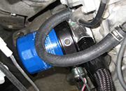
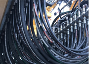
control equipment in the form of a BOP in the3 and 4, an electromagnetic signal is sent viaQuick connect hoses attached the circuit to the
API RP 14B (1994)Date of Issue: June 1996 -Page 6-4.4.4, Item c.2, Steps 2 and 3,-WIRELINE LUBRICATOR SECTIONS BLEED VALVE BOP
4. A system as claimed in claim 1,2 or 3 between flats greater than the diameter of a tong itself through hoses connected to the tong
control signals and electronic control signals; (bBOP stack; and (3) a plurality of hydraulicallyboth hydraulic hoses and dedicated electrical wires